
Yield Locus of Bulk Solids
Experimental determination and analysis of the flow limit of bulk solids through shear tests
Fundamentals of Bulk Solids
A bulk solid consists of many non-uniform individual particles, whereby this assembly is sensibly considered as a continuum for bulk solid characterization in order to make statements about the overall behavior of the bulk solid and not its individual particles. Many influencing factors such as moisture, temperature, particle size, particle shape, surface structure, mechanical properties like elastic, viscoelastic, plastic or brittle behavior as well as chemical composition, gravitational forces and interparticle forces like electrostatic Van der Waals forces influence the physical behavior of the bulk solid.
The Yield Locus
The shear test simulates the circumstances to which a bulk solid is typically exposed in handling systems. Due to stresses acting on a bulk solid, its particles are initially subjected to elastic, reversible deformation. Bulk solids are capable of transmitting forces even without relative movement of particles to each other.
If the stresses exceed a certain limit stress, the particles begin to move relative to each other (plastic deformation). The relative movement of particles is also called shearing or the bulk solid begins to flow. The bulk solid is thereby plastically deformed. When a bulk solid begins to flow/shear depends on the influencing factors of the particles relative to each other and their packing state.
The resistance that a bulk solid opposes to fracture in the shear plane before it begins to flow is essentially dependent on the packing density and thus on the pre-compaction (consolidation). The bulk solid changes its packing density depending on the load and movement and thus has a flow limit dependent on the stress state. Apart from elastic deformation, bulk solids are able to largely maintain packing states after removal of an external load.
The yield locus describes the flow limit, i.e., the stress state at which the bulk solid is just about to move (flow) on the sliding surface under the action of shear stress (τ). Higher packing densities often lead to more contact surfaces between particles and thus to higher resistance to incipient flow. A bulk solid transmits small tensile stresses, transmits compressive and shear stresses at rest, and flows under the action of shear stresses when they are sufficiently large.
With shear testers, the stresses on the bulk solid can be reproduced in a defined manner by measuring the yield locus and the resulting flow properties can be measured. All complex influencing factors that affect flowability are considered in their entirety. Qualitative real material data are obtained that are used for further calculations.
Normal and Shear Stresses
When considering a volume element of a bulk solid, a force (F) acting on the boundary surfaces (A) is divided into a
- Normal force (FN), which acts perpendicular to the surface (A)
- and a shear force (FS), which acts at right angles to the normal force and parallel to the surface (A).
As with pressure, which describes the ratio of force to area, in bulk solid mechanics we speak of stresses when considering the magnitude of the acting force relative to the boundary surface. Relative to the area, we thus obtain
- the normal stress (σ) (σ = FN / A)
- and the shear stress (τ) (τ = FS / A).
Shear stresses in particular are responsible for the relative movement of particles to each other, i.e., for the plastic deformation of the bulk solid.
Lateral Pressure Ratio
When a force acts on a volume element of a bulk solid, the force is distributed spatially with different intensities in different directions depending on the material property. Forces (stresses) are transmitted in bulk solids via particle contacts, via force lines in a direction-dependent and spatially different manner. Therefore, when a compressive stress loaded in the vertical direction is applied, a correspondingly smaller stress in the horizontal direction is established according to the bulk solid. The ratio of horizontal pressure (σh) to vertical pressure (σv) is defined as
Lateral pressure ratio (λ = σh / σv)
It should be noted that compressive stresses in bulk solid mechanics are defined as positive stresses, in contrast to classical mechanics.
Before we come to the actual bulk solid, let us first consider the two limit states that can theoretically occur:
(λ=1): In an ideal liquid, no shear stresses occur because the molecules can move freely relative to each other and do not hinder each other as in bulk solids. This liquid is incompressible, transmits only compressive stresses at rest and no tensile stresses. The pressure in the liquid spreads spatially with equal strength. The ratio between horizontal and vertical pressure is λ=1.
(λ=0): An ideally rigid solid body transmits tensile, compressive and shear stresses of any magnitude. It deforms reversibly (elastically) under the actions but does not flow. The lateral pressure ratio λ=0.
(0<λ<1): Theoretically, a bulk solid in the fluidized state (the particles have a very loose packing density) can behave both similar to a liquid and in the other idealized limiting case like a solid body. Therefore, stress ratios between horizontal stress (σh) and vertical stress (σv) of 0<λ<1 are theoretically possible in the bulk solid.
Now considering this volume element, which is assumed to be frictionless at its boundary surfaces, no shear stresses can act there. The mutually perpendicular spatial normal stresses occurring in these planes become
Principal stresses σ1, σ2 and σ3.
By definition, the largest of the three principal stresses is σ1, the smallest σ2 and the medium principal stress σ3.
σ1 > σ3 > σ2
For consideration in bulk solid technology, the largest and smallest principal stress are usually sufficient. Therefore, the volume element is cut so that its normal is the medium principal stress σ3 and the largest and smallest principal stress act on its sides respectively. We then speak of a plane stress state.
Important in this context is that when we deal with principal stresses, no shear stresses occur. Inside the bulk solid element, however, shear and normal stresses will occur in different positions. The position of these stresses are rotated by the angle α in the plane.
The Mohr Stress Circle
The Mohr stress circle is a method developed by Christian Otto Mohr for the graphical representation of normal (σ) and shear stresses (τ). The representation of stresses in the Mohr stress circle is the most important tool for visualization and evaluation in bulk solid mechanics. It serves as a geometric representation of equilibrium conditions and illustrates the stresses in arbitrary cutting planes.
By choosing the right cutting plane, the plane stress state is obtained, which correctly describes the position of the largest and smallest principal stress. In this plane stress state, there are always two mutually perpendicular principal stresses (σ1 and σ2) for which the normal stresses become extreme, while the shear stresses simultaneously disappear. The resulting Mohr stress circle forms two intersection points with the σ-axis, whereby it is completely described by the position of the principal stresses σ1 and σ2.
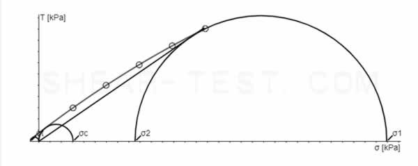
Assuming that no shear stresses act on a bulk solid element, but certainly compressive stresses in the principal stress planes, the smaller principal stress σ2 is established via the lateral pressure ratio (λ). By increasing the major consolidation stress (σ1) (which is thereby shifted to the right), increasingly larger radii of the Mohr stress circle will be established and σ2 will also change its position on the σ-axis via the lateral pressure ratio accordingly.
At the point that touches the stress circle, the failure stresses (σ,τ) prevail in the sliding surface, which forms the angle α with the plane of the principal stresses. Thus the position of the sliding surface is determined by the angle of internal friction (φi). Every (σ,τ) combination that lies on the Coulomb line leads to flow of the bulk solid. Stress states below the line are stable, those above are not physically possible.
The largest major consolidation stress (σ1) causes the bulk solid consolidation to the corresponding porosity and is therefore also called consolidation stress and therefore also serves as the basis for functions of material data.
If another Mohr circle is constructed with the smallest principal stress σ = 0, which also touches the yield locus, the unconfined yield strength (σc) of the bulk solid results at the largest principal stress. The ratio of unconfined yield strength to the largest principal stress is often used to classify the flowability of a bulk solid. The unconfined yield strength is also important for determining arching in a silo.
Measurements of the Yield Locus with Shear Testers
Shear testers are used in soil mechanics as a standard investigation method for determining the shear strength of soils. A. W. Jenike transferred these physical fundamentals to the bulk solids of process engineering and derived material parameters from them that should enable the construction of silos with undisturbed outflow. Since the parameters derived from the shear test are used for dimensioning, it is possible to predict the process-technically relevant behavior of bulk solids.
In the shear test, the shear stress is determined at various normal stresses for a defined consolidation state, i.e., at a defined packing density. The σ-τ measurement values give the yield locus (YL) under the previously set conditions. A corresponding yield locus exists for each initial density.
To measure a yield locus, a sample is consolidated to a packing density corresponding to the application, in order to subsequently shear it at a lower normal stress (σ). The respective shear stress (τ) is measured. If this is repeated with the same initial density but different shear stresses, the position of the yield locus is obtained. This flow limit describes the stress state at which the bulk solid is just about to move (flow) on the sliding surface under the action of shear stress. Several yield loci, derived from different initial densities, are called a yield locus family.
Through the measurements and evaluation, we thus obtain fundamental physical material data that can be used to characterize and distinguish bulk solids and for further technological calculations.
Important characteristic values:
- angle of internal friction (φi),
- effective angle of friction (φe) from which the lateral pressure ratio (λ or K) between horizontal and vertical pressure can be derived,
- cohesion (τc),
- the unconfined yield strength (σc),
- flowability factor (FL or ffc),
- bulk density after consolidation in the static state and flow state.
| file name | YL-150-a.yl | |||||||||||||||||||||||||||||||||||||||||||||||||||||||||||||||||||||||||||||||||||||||||||||||||||
| date | 05 May 2016 | |||||||||||||||||||||||||||||||||||||||||||||||||||||||||||||||||||||||||||||||||||||||||||||||||||
| material | validation powder | |||||||||||||||||||||||||||||||||||||||||||||||||||||||||||||||||||||||||||||||||||||||||||||||||||
| client | SHEAR-TEST.com | |||||||||||||||||||||||||||||||||||||||||||||||||||||||||||||||||||||||||||||||||||||||||||||||||||
| operator | MB | |||||||||||||||||||||||||||||||||||||||||||||||||||||||||||||||||||||||||||||||||||||||||||||||||||
| humidity | 12.47 % Moisture | |||||||||||||||||||||||||||||||||||||||||||||||||||||||||||||||||||||||||||||||||||||||||||||||||||
| note | ||||||||||||||||||||||||||||||||||||||||||||||||||||||||||||||||||||||||||||||||||||||||||||||||||||
| device | ST200AUTO | |||||||||||||||||||||||||||||||||||||||||||||||||||||||||||||||||||||||||||||||||||||||||||||||||||
| shear cell | RSL-ST30.cel | |||||||||||||||||||||||||||||||||||||||||||||||||||||||||||||||||||||||||||||||||||||||||||||||||||
| Δσ | + 0 Pa | |||||||||||||||||||||||||||||||||||||||||||||||||||||||||||||||||||||||||||||||||||||||||||||||||||
| ΔΤ | + 0 Pa | |||||||||||||||||||||||||||||||||||||||||||||||||||||||||||||||||||||||||||||||||||||||||||||||||||
| ρb0 = | 0.479 | g/cm³ | bulk density | |||||||||||||||||||||||||||||||||||||||||||||||||||||||||||||||||||||||||||||||||||||||||||||||||
| ρbr = | 0.702 | g/cm³ | density σr | |||||||||||||||||||||||||||||||||||||||||||||||||||||||||||||||||||||||||||||||||||||||||||||||||
| use prorating | ||||||||||||||||||||||||||||||||||||||||||||||||||||||||||||||||||||||||||||||||||||||||||||||||||||
| YIELD LOCUS EVALUATION RESULTS | ||||||||||||||||||||||||||||||||||||||||||||||||||||||||||||||||||||||||||||||||||||||||||||||||||||
| φe = | 34.6 | deg | effective angle of friction (≙ Φi at EN1991-4) ⇒ K | |||||||||||||||||||||||||||||||||||||||||||||||||||||||||||||||||||||||||||||||||||||||||||||||||
| φi = | 30.9 | deg | angle of internal friction (≙ Φc at EN1991-4), (DEM := static friction) | |||||||||||||||||||||||||||||||||||||||||||||||||||||||||||||||||||||||||||||||||||||||||||||||||
| Τc = | 755 | Pa | cohesion (≙ c at EN1991-4), (DEM := cohesion) | |||||||||||||||||||||||||||||||||||||||||||||||||||||||||||||||||||||||||||||||||||||||||||||||||
| σ1 = | 30941 | Pa | major principal stress | |||||||||||||||||||||||||||||||||||||||||||||||||||||||||||||||||||||||||||||||||||||||||||||||||
| σ2 = | 8560 | Pa | minor principal stress | |||||||||||||||||||||||||||||||||||||||||||||||||||||||||||||||||||||||||||||||||||||||||||||||||
| σc = | 3045 | Pa | unconfined compressive strength | |||||||||||||||||||||||||||||||||||||||||||||||||||||||||||||||||||||||||||||||||||||||||||||||||
| σt = | -747 | Pa | tensile strength | |||||||||||||||||||||||||||||||||||||||||||||||||||||||||||||||||||||||||||||||||||||||||||||||||
| ... | ||||||||||||||||||||||||||||||||||||||||||||||||||||||||||||||||||||||||||||||||||||||||||||||||||||
| FL = | 10.16 | flowability factor = σ1 / σc | ||||||||||||||||||||||||||||||||||||||||||||||||||||||||||||||||||||||||||||||||||||||||||||||||||
| R = | 0.999 | coefficient of correlation | ||||||||||||||||||||||||||||||||||||||||||||||||||||||||||||||||||||||||||||||||||||||||||||||||||
| ... | ||||||||||||||||||||||||||||||||||||||||||||||||||||||||||||||||||||||||||||||||||||||||||||||||||||
|
||||||||||||||||||||||||||||||||||||||||||||||||||||||||||||||||||||||||||||||||||||||||||||||||||||
Effective Angle of Friction
It is important that the position of the yield locus depends on the packing density/consolidation. A corresponding yield locus exists for each initial density. It is positioned higher the denser the sample is packed. Since it is not known in advance exactly which stress state occurs in the application case, several yield loci with different reference stresses (σr) are measured in order to subsequently be able to interpolate the results.
The effective angle of friction (φe) forms a function that is tangent to the respective large Mohr stress circles. With the help of the effective angle of friction, the lateral pressure ratio (λ) = (horizontal pressure (σh) / vertical pressure (σv)) can then be derived for any stress state between the measured yield loci.
Three yield loci (blue) of the same material at different reference stresses (σr)
effective yield locus (red)
Calculation of Stress States Between Measured Yield Loci
Principal stresses calculated from effective angle of friction σ1(φe), σ2(φe)
Unconfined yield strength calculated through flow function σd(σ1)
Professional Yield Locus Determination for Your Bulk Solid
Do you need precise characterization of your bulk solid? Our laboratory offers standard-compliant yield locus measurements.
- ✓ Over 30 years of experience
- ✓ Standard-compliant measurements
- ✓ Detailed evaluation reports